


Microchip Technology PIC16F152 Microcontrollers
Microchip Technology PIC16F152 Microcontrollers are available in various packages for cost-sensitive sensors and real-time control applications. The PIC16F152 has a simplified feature set that includes a 10-bit Analog-to-Digital Converter (ADC). Other features include a Peripheral Pin Select (PPS), digital communication peripherals, timers, and waveform generators. Memory features include Memory Access Partition (MAP) to support data protection and bootloader applications. A Device Information Area (DIA) stores Fixed Voltage Reference (FVR) offset values to improve ADC accuracy.
Features
- Core Features
- C Compiler Optimized RISC Architecture
- Operating Speed:
- DC – 32MHz clock input
- 125ns minimum instruction time
- 16-Level Deep Hardware Stack
- Low-Current Power-on Reset (POR)
- Configurable Power-up Timer (PWRT)
- Brown-out Reset (BOR)
- Watchdog Timer (WDT)
- Memory
- Up to 28KB of Program Flash Memory
- Up to 2KB of Data SRAM Memory
- Memory Access Partition (MAP): The Program Flash Memory can be partitioned into:
- Application Block
- Boot Block
- Storage Area Flash (SAF) Block
- Programmable Code Protection and Write Protection
- Device Information Area (DIA) Stores:
- Fixed Voltage Reference (FVR) measurement data
- Microchip unique identifier
- Device Characteristics Area (DCI) Stores:
- Program/erase row sizes
- Pin count details
- Direct, Indirect, and Relative Addressing Modes
- Operating Characteristics
- Operating Voltage Range:
- 1.8V to 5.5V
- Temperature Range:
- Industrial: -40°C to 85°C
- Extended: -40°C to 125°C
- Operating Voltage Range:
- Power-Saving Functionality
- Sleep:
- Reduce device power consumption
- Reduce system electrical noise while performing ADC conversions
- Low-Power Mode Features:
- Sleep:
- < 900nA typical @ 3V/25°C (WDT enabled)
- < 600NA typical @ 3V/25°C (WDT disabled)
- Operating Current:
- 48µA typical @ 32kHz, 3V/25°C
- < 1mA typical @ 4MHz, 5V/25°C
- Sleep:
- Clocking Structure
- High-Precision Internal Oscillator Block (HFINTOSC):
- Selectable frequencies up to 32MHz
- ±2% at calibration
- Internal 31kHz Oscillator (LFINTOSC)
- External High-Frequency Clock Input:
- Two External Clock (EC) power modes
- High-Precision Internal Oscillator Block (HFINTOSC):
- Digital Peripherals
- Two Capture/Compare/PWM (CCP) modules:
- 16-bit resolution for Capture/Compare modes
- Two Pulse-Width Modulators (PWM):
- 10-bit resolution
- Independent pulse outputs
- 10-bit resolution for PWM mode
- One Configurable 8/16-Bit Timer (TMR0)
- One 16-Bit Timer (TMR1) with Gate Control
- One 8-Bit Timer (TMR2) with Hardware Limit Timer (HLT)
- One Enhanced Universal Synchronous Asynchronous Receiver Transmitter (EUSART):
- RS-232, RS-485, LIN compatible
- Auto-wake-up on Start
- One Master Synchronous Serial Port (MSSP):
- Serial Peripheral Interface (SPI) mode
- Slave Select Synchronization
- Inter-Integrated Circuit (I2C) mode
- 7/10-bit addressing modes
- Peripheral Pin Select (PPS):
- Enables pin mapping of digital I/O
- Device I/O Port Features:
- Up to 35 I/O pins
- 1 input-only pin
- Individual I/O direction, open-drain, input threshold, slew rate, and weak pull-up control
- Interrupt-on-Change (IOC) on all pins
- One External Interrupt pin
- Two Capture/Compare/PWM (CCP) modules:
- Analog Peripherals
- Analog-to-Digital Converter (ADC):
- 10-bit resolution
- Up to 28 external input channels
- Two internal input channels
- Internal ADC oscillator (ADCRC)
- Operates in Sleep
- Selectable Auto-Conversion Trigger sources
- Fixed Voltage Reference (FVR):
- Selectable 1.024V, 2.048V, and 4.096V output levels
- Internally connected to ADC
- Analog-to-Digital Converter (ADC):
- Programming/Debug Features
- In-Circuit Serial Programming™ (ICSP™) via Two Pins
- In-Circuit Debug (ICD) with One Breakpoint via Two Pins
- Debug Integrated On-Chip
Related Products
Microchip Technology PIC16F15244 8-Bit Microcontrollers
Compact, 20-pin MCUs ideal for simple real-time control and sensor-based applications.
Microchip Technology 8-Bit PIC® & AVR® Microcontrollers
Versatile microcontroller families with an extensive portfolio of development and support tools.
Development Tools
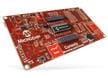
Microchip Technology Curiosity 8-Bit Development Board (DM164137)
Full featured development tool for Microchip 8-pin, 14-pin, and 20-pin 8-bit PIC® Microcontrollers.
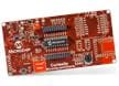
Microchip Technology Curiosity HPC Development Board (DM164136)
Supports Microchip's 28- and 40-pin 8-bit PIC® MCUs and features two unique PDIP sockets.
Block Diagram

Published: 2020-10-15
| Updated: 2025-06-13