Class D Audio Amplifiers: What, Why, and How
By Eric Gaalaas,
Analog Devices
Featured Products
Featured Suppliers
Resources
Class D amplifiers, first proposed in 1958, have become increasingly popular in recent years. What are Class D
amplifiers? How do they compare with other kinds of amplifiers? Why is Class D of interest for audio? What is
needed to make a "good" audio Class D amplifier? What are the features of ADI's Class D amplifier
products?
Audio Amplifier Background
The goal of audio amplifiers is to reproduce input audio signals at sound-producing output elements, with desired
volume and power levels-faithfully, efficiently, and at low distortion. Audio frequencies range from about 20 Hz
to 20 kHz, so the amplifier must have good frequency response over this range (less when driving a band-limited
speaker, such as a woofer or a tweeter). Power capabilities vary widely depending on the application, from
milliwatts in headphones, to a few watts in TV or PC audio, to tens of watts for "mini" home stereos
and automotive audio, to hundreds of watts and beyond for more powerful home and commercial sound systems-and to
fill theaters or auditoriums with sound.
A straightforward analog implementation of an audio amplifier uses transistors in linear mode to create an output
voltage that is a scaled copy of the input voltage. The forward voltage gain is usually high (at least 40 dB).
If the forward gain is part of a feedback loop, the overall loop gain will also be high. Feedback is often used
because high loop gain improves performance- suppressing distortion caused by nonlinearities in the forward path
and reducing power supply noise by increasing the power-supply rejection (PSR).
The Class D Amplifier Advantage
In a conventional transistor amplifier, the output stage contains transistors that supply the instantaneous
continuous output current. The many possible implementations for audio systems include Classes A, AB, and B.
Compared with Class D designs, the output-stage power dissipation is large in even the most efficient linear
output stages. This difference gives Class D significant advantages in many applications because the lower power
dissipation produces less heat, saves circuit board space and cost, and extends battery life in portable
systems.
Linear Amplifiers, Class D Amplifiers, and Power Dissipation
Linear-amplifier output stages are directly connected to the speaker (in some cases via capacitors). If bipolar
junction transistors (BJTs) are used in the output stage, they generally operate in the linear mode, with large
collector-emitter voltages. The output stage could also be implemented with MOS transistors, as shown in Figure
1.
Figure 1: CMOS linear output stage.
Power is dissipated in all linear output stages, because the process of generating VOUT unavoidably
causes nonzero IDS and VDS in at least one output transistor. The amount of power
dissipation strongly depends on the method used to bias the output transistors.
The Class A topology uses one of the transistors as a dc current source, capable of supplying the maximum audio
current required by the speaker. Good sound quality is possible with the Class A output stage, but power
dissipation is excessive because a large dc bias current usually flows in the output-stage transistors (where we
do not want it), without being delivered to the speaker (where we do want it).
The Class B topology eliminates the dc bias current and dissipates significantly less power. Its output
transistors are individually controlled in a push-pull manner, allowing the MH device to supply positive
currents to the speaker, and ML to sink negative currents. This reduces output stage power dissipation, with
only signal current conducted through the transistors. The Class B circuit has inferior sound quality, however,
due to nonlinear behavior (crossover distortion) when the output current passes through 0 and the transistors
are changing between the on and off conditions.
Class AB, a hybrid compromise of Classes A and B, uses some dc bias current, but much less than a pure Class A
design. The small dc bias current is sufficient to prevent crossover distortion, enabling good sound quality.
Power dissipation, although between Class A and Class B limits, is typically closer to Class B. Some control,
similar to that of the Class B circuit, is needed to allow the Class AB circuit to supply or sink large output
currents.
Unfortunately, even a well-designed class AB amplifier has significant power dissipation, because its midrange
output voltages are generally far from either the positive or negative supply rails. The large drain-source
voltage drops thus produce significant IDS X VDS instantaneous power dissipation.
Figure 2: Class D open-loop-amplifier block
diagram.
Since most audio signals are not pulse trains, a modulator must be included to convert the audio input into
pulses. The frequency content of the pulses includes both the desired audio signal and significant
high-frequency energy related to the modulation process. A low-pass filter is often inserted between the output
stage and the speaker to minimize electromagnetic interference (EMI) and avoid driving the speaker with too much
high frequency energy. The filter (Figure 3) needs to be lossless (or nearly so) in order to retain the
power-dissipation advantage of the switching output stage. The filter normally uses capacitors and inductors,
with the only intentionally dissipative element being the speaker.
Figure 3: Differential switching
output stage and LC low-pass filter.
Figure 4 compares ideal output-stage power dissipation (PDISS) for Class A and Class B amplifiers with
measured dissipation for the AD1994 Class D amplifier, plotted against power delivered to the speaker
(PLOAD), given an audio-frequency sine wave signal. The power numbers are normalized to the power
level, PLOAD max, at which the sine is clipped enough to cause 10% total harmonic distortion (THD).
The vertical line indicates the PLOAD at which clipping begins.
Significant differences in power dissipation are visible for a wide range of loads, especially at high and
moderate values. At the onset of clipping, dissipation in the Class D output stage is about 2.5 times less than
Class B, and 27 times less than Class A. Note that more power is consumed in the Class A output stage than is
delivered to the speaker-a consequence of using the large dc bias current.
Output-stage power efficiency, Eff, is defined as
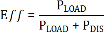
Figure 4: Power
dissipation in Class A, Class B, and Class D output stages.
At the onset of clipping, Eff = 25% for the Class A amplifier, 78.5% for the Class B amplifier, and 90%
for the Class D amplifier (see Figure 5). These best-case values for Class A and Class B are the ones often
cited in textbooks.
Figure 5: Power efficiency
of Class A, Class B, and Class D output stages.
The differences in power dissipation and efficiency widen at moderate power levels. This is important for audio,
because longterm average levels for loud music are much lower (by factors of five to 20, depending on the type
of music) than the instantaneous peak levels, which approach PLOADmax. Thus, for audio
amplifiers, [PLOAD = 0.1 X PLOADmax] is a reasonable average power level at which
to evaluate PDISS. At this level, the Class D output-stage dissipation is nine times less than Class
B, and 107 times less than Class A.
For an audio amplifier with 10-W PLOADmax, an average PLOAD of 1 W can be
considered a realistic listening level. Under this condition, 282 mW is dissipated inside the Class D output
stage, vs. 2.53 W for Class B and 30.2 W for Class A. In this case, the Class D efficiency is reduced to
78%-from 90% at higher power. But even 78% is much better than the Class B and Class A efficiencies-28% and 3%,
respectively.
These differences have important consequences for system design. For power levels above 1 W, the excessive
dissipation of linear output stages requires significant cooling measures to avoid unacceptable
heating-typically by using large slabs of metal as heat sinks, or fans to blow air over the amplifier. If the
amplifier is implemented as an integrated circuit, a bulky and expensive thermally enhanced package may be
needed to facilitate heat transfer. These considerations are onerous in consumer products such as flat-screen
TVs, where space is at a premium- or automotive audio, where the trend is toward cramming higher channel counts
into a fixed space.
For power levels below 1 W, wasted power can be more of a difficulty than heat generation. If powered from a
battery, a linear output stage would drain battery charge faster than a Class D design. In the above example,
the Class D output stage consumes 2.8 times less supply current than Class B and 23.6 times less than Class
A-resulting in a big difference in the life of batteries used in products like cell phones, PDAs, and MP3
players.
For simplicity, the analysis thus far has focused exclusively on the amplifier output stages. However, when all
sources of power dissipation in the amplifier system are considered, linear amplifiers can compare more
favorably to Class D amplifiers at low output-power levels. The reason is that the power needed to generate and
modulate the switching waveform can be significant at low levels. Thus, the system-wide quiescent dissipation of
well-designed low-to-moderate-power Class AB amplifiers can make them competitive with Class D amplifiers. Class
D power dissipation is unquestionably superior for the higher output power ranges, though.


